Calibrating a Custom Load Cell w/ Raetech S.G. Amplifier

Introduction:
We want to measure the force transferred by a Swaybar drop link. The part is 3/4" od, 7/16" id, 5" long. Material is 6061 Aluminum with 1/2" rod ends on both ends. Typical loads are expected to be in the 700 lb range with potential excursions to twice that value. RAETECH's Programmable Strain Gage Amplifier will be used to supply bridge excitation and create a high level 0-5v output.

A pair of 2-axis strain gages were installed directly opposite each other on the surface of the part. The gages are arranged with a longitudinal element on each side of the part to measure link forces and transverse elements to correct for thermo expansion. The Raetech S.G. Amplifier was bonded to the part and the gages wired to form a full bridge. Wire Leads will be potted to provide moisture protection and vibration resistance before installing in vehicle.
Gain Adjustment:
To adjust the load cell sensitivity we need to apply a know load and measure the response. We need at least two points which should span the intended operating range. This can be accomplished as simply as hanging a know load: 'dead weight' from the load cell or by applying a force measured by a precision reference load cell. Here we will use the second technique to measure the voltage output when 1600 lb load is applied in tension, then repeated in compression.

The amp was initially programmed with a Gain of 500, an Offset of 2.5v and no temperature correction. The Offset was adjusted to produce 2.5v No-Load output, removing any static strain gage bridge imbalance. Baseline room temperature rate tests were conducted. Based on those results the Gain was increased to 545 to create an output sensitivity of 800 lb/v. This gives a usable range of +/- 1900 lb for an output swing of 0.1 to 4.9v. Examples of using Raetech Programing Interface.
Temperature Sensitivity:

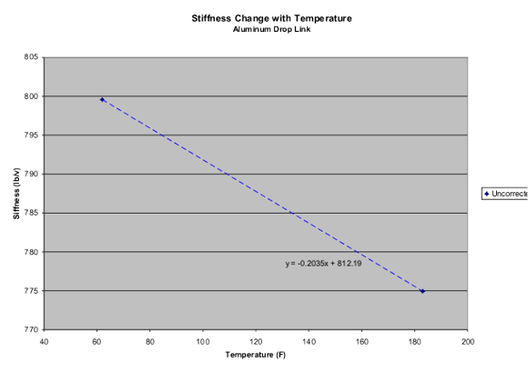
We have adjusted the room temperature gain to provide the desired rate. To improve accuracy of the in actual usage we will check the sensitivity at a higher temperature. In order to accomplish this we setup a tension test fixture that fits in an oven. The part will be baseline tested at room temperature. Then it will be stabilized at the higher temperature and the test repeated.
The load sensitivity of our part changes more than 2.5% over a 100 degF temperature range. These results demonstrate that the material stiffness, or modulus changes with temperature. Reference material showing the modulus change with temperature is difficult to find. We have an example here for 6061 Aluminum. The data in the chart is consistent with our measurements. Reference data for some other common materials.

Temperature Correction:
RAETECH's S.G. Amplifier allows us to correct for the modulus change by programming a temperature dependent gain. We repeat the Hot and Room temperature tests and add the results to our chart. Next, we determine if we are in an allowable error tolerance, if not we repeat exercise. Should the linear correction not provide adequate accuracy a non-linear gain table can be created using either measured or reference data.

Zero Drift Correction:
Small differences in thermal expansion between the strain gage and the base material can introduce strains and temperature changes. Surface curvature, glue bond thickness and other parameters can influence results.
The Zero Drift test is left for last since the combination of any static bridge imbalance multiplied by a temperature dependent gain will result in an output that change with temperature. The No-Load output error can be removed using a temperature dependent offset.
We need to measure the No-Load output at a minimum of two temperatures, preferably near the upper and lower limits of our operating range. A linear curve fit can be conducted to fill in the offset temperature table. To improve accuracy the no-load output can be measured at additional temperature points in the working range. You can even run a temperature sweep across the operating range. Care must be taken that the part is at a constant temperature at any point during the sweep to avoid introducing thermal stresses. This requires the sweep to be conducted slowly.
We can use the programmers live data mode to display the sensor's no-load output at two temperatures. Connect the programmer and let the system stabilize at the first temperature. Note, we are doing the higher temperature first since some stress relieving may occur in the gage glue bond on the first heat cycle.
Then stabilize at the second temperature.
Plot the results to find the voltage change with temperature. The programming interface can be used to create an Offset that changes with temperature that will remove the No-Load voltage change with temperature
The No-Load Drift test should be repeated to verify the adjustments bring the sensor within performance requirements. Often a second fine adjustment may be required.
Results:
Load Cell Performance:
| Temperature Properties | ||
| Before | After | |
| Span Shift %/°F | -0.0256 | -0.0009 |
| Zero Drift %R.O./°F | 0.0073 | -0.0003 |
We have significantly improved the accuracy of our custom load cell by using the programmable temperature correction provided by Raetech's SG Amplifier to remove effects due to material stiffness change and No-Load output drift.


